
A blind hole gives chips nowhere to exit, so the tap’s flute direction, chamfer length and drilled depth directly affect torque, thread quality and breakage risk. By the end, you will be able to compare tap geometries, calculate usable hole depth and select a tool and tapping cycle that match the material and machine.
Key takeaways
- Use spiral flutes to lift chips away from a blind-hole bottom.
- Allow space for the chamfer and unthreaded hole depth.
- Choose forming taps only when material and hole conditions suit them.
- Match tap size, pitch, coating and cutting data to the workpiece.
How spiral flutes move chips out of a blind hole
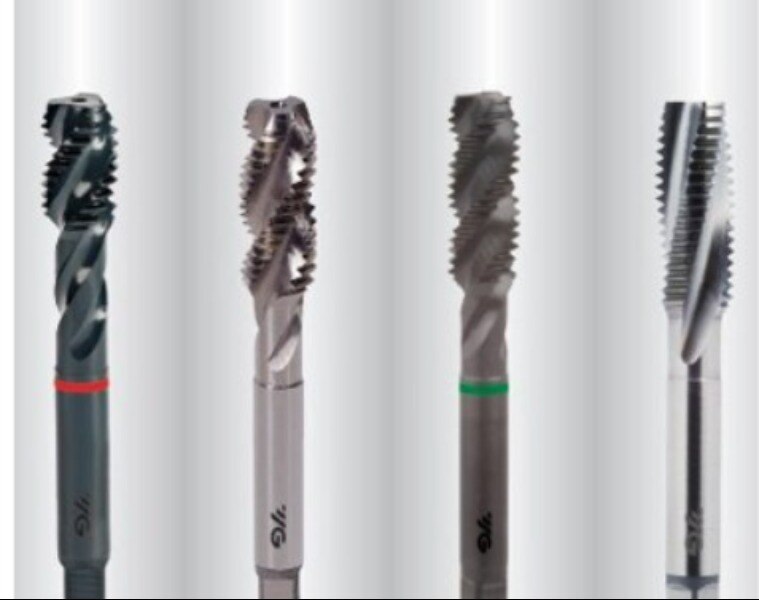
A HSS spiral-flute tap carries chips upward toward the shank instead of pushing them into the blind-hole bottom. That reverse chip path is the main advantage in blind-hole threading: it reduces packing where thread depth is close to the drilled depth and leaves less room for chips to accumulate.
| Tap geometry | Chip movement | Blind-hole consequence | Typical use |
|---|---|---|---|
| HSS spiral-flute tap | Back toward the shank | Clears chips from the bottom and reduces packing | Blind holes producing continuous chips |
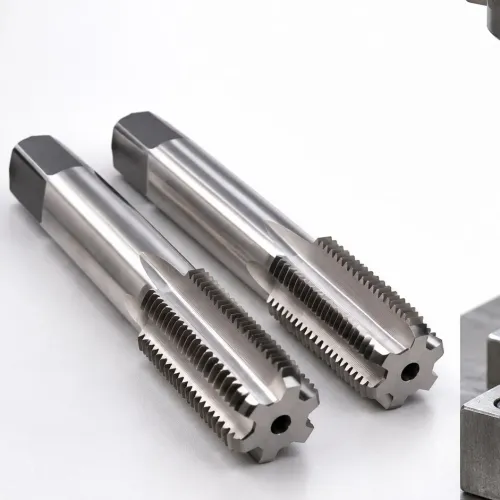
| Straight-flute tap | Along the flutes, with limited lifting action | Chips can collect in the hole and jam the tap | Short, shallow holes or materials with manageable chips |
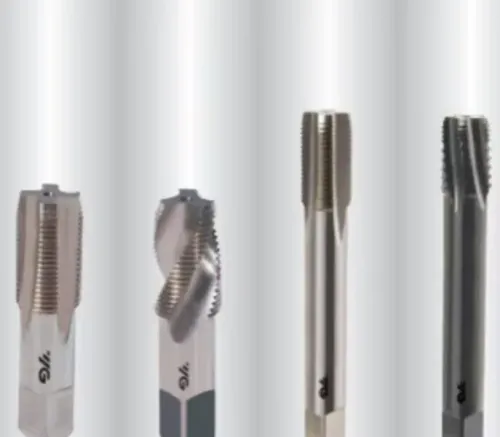
| Spiral-point tap | Forward through the hole | Chips are driven ahead into space the blind hole does not provide | Through holes |
| Forming tap | No cutting chips | Avoids chip evacuation, but needs a larger tap-drill diameter and ductile material | Ductile materials suited to chipless threading |
Spiral flute geometry does not let the tap reach the physical bottom safely. The chamfered section makes incomplete-height threads, while the drill point, hole taper and evacuated chips consume additional depth; forcing the tap beyond that clearance causes torque spikes or breakage.
Use this geometry for ductile materials that produce long chips, interrupted holes, and machines with rigid tapping or synchronized feed. Feed must match the thread pitch, because spindle-to-axis mismatch overloads the tap before chip evacuation can protect it.
Why hole depth and chamfer length determine the usable thread
The drilled-hole depth must exceed the required usable thread depth by the allowances that keep the tap from bottoming. Specify it from the full-form thread requirement, not from the nominal hole depth alone.
- Full-form thread length: the axial length that must have complete thread height.
- Tap chamfer and run-out: the entry section cuts incomplete or developing threads, while the run-out does not provide the specified thread profile.
- Bottom clearance: empty space below the tap’s cutting end for safe reversal and chip accumulation.
- Drill-point allowance: extra depth for the conical drill point or taper that was not removed during drilling.
A practical calculation is: drilled-hole depth = usable thread depth + tap chamfer length + run-out allowance + bottom clearance + drill-point allowance. Confirm the tap manufacturer’s chamfer dimension rather than estimating it from the nominal diameter.
If the hole is drilled only to the required thread length, the chamfer consumes part of that distance and leaves too little full-form thread. The tap can also contact the tapered bottom, packed chips, or uncut material, causing a torque spike and breakage.
A long-chamfer tap starts cutting gradually but needs more depth. A short-chamfer or bottoming-style tap produces usable thread closer to the bottom, but fewer teeth carry the load. Choose the latter only when the hole depth cannot accommodate a longer tap chamfer and the machine can control the tapping cycle accurately.
When to choose a spiral-flute, straight-flute or forming tap
Choose a spiral-flute tap for a blind hole in a ductile material that produces continuous chips, especially when the threaded depth approaches the drilled depth. Its helical flutes lift chips toward the shank instead of packing them against the hole bottom.
| Tap type | Workpiece and hole condition | Chip behaviour and decision |
|---|---|---|
| Spiral-flute tap | Blind holes, interrupted holes, aluminium, mild steel and other materials producing long chips | Pulls chips backward; choose it when controlled spindle-feed synchronisation and reliable chip evacuation are available |
| Straight-flute tap | Short blind holes, shallow threads, free-cutting materials or materials producing short, broken chips | Holds chips in the flutes; choose it when chip volume is low, because packing can break the tap in a deep hole |
| Spiral-point tap | Through holes with an exit for chips | Pushes chips forward; choose it for through holes, not a blind hole where chips have nowhere to go |
| Forming tap or roll tap | Ductile materials that support chipless thread forming and a correctly sized, larger tap-drill diameter | Produces no cutting chips, but needs higher forming torque and adequate material flow; reject it for brittle or insufficiently ductile stock |
A spiral-flute tap is the wrong choice for a through hole where a spiral-point tap can eject chips directly, or for a ductile job better suited to forming. It also loses its advantage when the machine cannot synchronise feed with pitch, because feed error creates torque spikes in the confined hole.
HSS identifies the substrate, not the complete specification. Match flute helix, chamfer, coating, polish and cutting lubricant to the material; aluminium may need a polished or coated geometry to prevent built-up edge.
How to run a spiral-flute tap without overloading it
Run the tap in rigid tapping mode, or use a correctly synchronized tension-compression holder when the machine cannot maintain exact spindle-to-feed control. Set tapping feed to pitch: feed in mm/min = spindle speed in rev/min × pitch in mm. For an M8 × 1.25 tap at 500 rpm, program 625 mm/min.
A feed mismatch forces the tap to cut while the machine pushes or pulls against its thread. In a blind hole, that error combines with limited chip space and creates torque spikes, chip packing and tap breakage.
- Confirm the drilled hole reaches beyond the intended thread depth, including the drill-point taper and the tap’s chamfer length.
- Align the tap with the hole; excessive runout makes a high-helix tap bind and increases axial pull.
- Use a sharp, suitable HSS spiral-flute tap with cutting fluid that matches the workpiece. Apply enough lubricant to prevent built-up edge, especially in aluminium; dry cutting can weld chips to the flutes.
- Set a controlled reversal and retract without dwelling at the blind-hole bottom. Never use the bottom as a depth stop.
| Tool condition | Chip movement | Running consequence |
|---|---|---|
| Spiral-flute tap | Back toward the shank | Suits blind holes when feed, alignment and lubrication are controlled |
| Straight-flute tap | Along the flutes with limited lifting action | Chips can accumulate at the bottom and raise torque |
| Spiral-point tap | Forward ahead of the tap | Best for through holes; unsuitable when chips have nowhere to exit |
Higher helix angles lift chips more aggressively but demand better alignment and lubrication.
A practical checklist for specifying the right HSS spiral-flute tap
A wrong pitch or missing bottom allowance can break an otherwise suitable tap. Confirm these details before ordering or programming:
- Thread standard and designation: ISO metric, Unified UNC/UNF, or another standard; nominal diameter; pitch; and tolerance class such as 6H.
- Required full-form thread length, tap chamfer length, run-out, and the drilled-hole depth below the finished thread. Do not program to nominal hole depth alone.
- Tap dimensions: cutting diameter, overall length, flute length, shank diameter, square size, and reach needed to clear the fixture.
- Workpiece material, hardness, ductility, interrupted-hole condition, and whether the material makes continuous chips. Specify flute helix, chamfer form, HSS grade, and tap coating against these details.
- Tap-drill diameter and lubrication. A forming tap needs a larger specified drill and ductile material; do not substitute it for a cutting tap without checking torque.
- Machine interface: rigid tapping capability or a correctly synchronized tension-compression holder, spindle speed range, coolant delivery, and the programmed feed. For a single-start thread, feed per revolution must equal the pitch.
- Toolholder connection, gauge length, spindle orientation, and clearance to the hole bottom.
| Specification | Confirm | Why it matters |
|---|---|---|
| Thread | Standard, diameter, pitch, tolerance class | Prevents an unworkable or undersize thread |
| Tool | Chamfer, reach, coating, flute helix | Controls usable thread and chip movement |
| Machine | Holder, synchronization, feed, coolant | Prevents torque spikes and tap breakage |
R.S. Tools & Engineers Pvt. Ltd. can help turn these parameters into a tool request rather than an ambiguous “HSS tap” order.
Related product
 | HSS Spiral Flute Tap Product Image Supply Ability:500 Per Day Shape:Straight Material:High Speed Steel Color:Black, Silver and Grey Usage:For Cutting, Shaping and... View product → |
Frequently asked questions
How do spiral flutes move chips out of a blind hole?
The helical flutes carry chips upward toward the shank, reducing chip packing at the blind-hole bottom.
How do hole depth and chamfer length affect usable thread?
The drilled depth must accommodate the tap chamfer, chip space and any unthreaded section, so usable thread is shorter than hole depth.
When should you choose a spiral-flute, straight-flute or forming tap?
Choose a spiral-flute tap for blind holes, a straight-flute tap for many through-holes or short-chipping materials, and a forming tap when the material and hole size support thread forming.
How can you prevent overloading a spiral-flute tap?
Use the correct tap drill, cutting speed, alignment, lubrication and programmed depth, then reverse smoothly without forcing the tap.