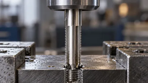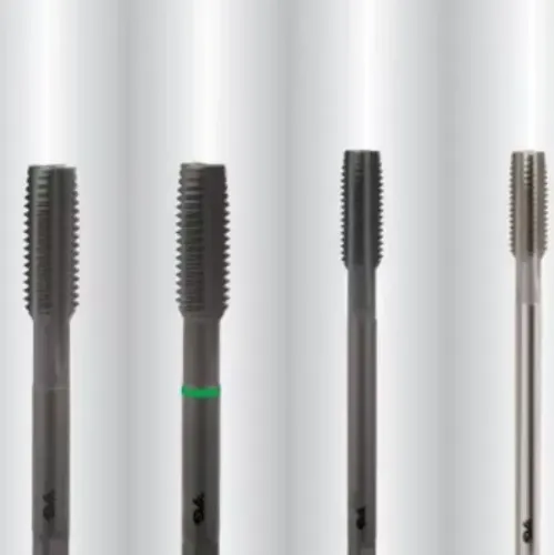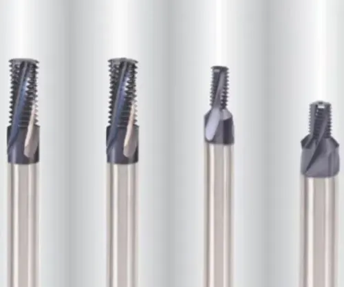

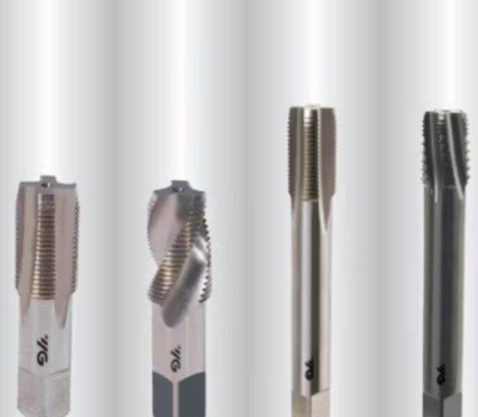
A pipe tap can cut the correct nominal size and still produce a leaking joint if the thread standard, taper, sealing method or finished depth is wrong. You will be able to identify the thread system, specify the tap accurately, match it to the workpiece and verify the completed connection before it enters service.
Key takeaways
- Confirm the thread standard, pitch, angle and taper before ordering a pipe tap.
- Match the tap to the joint’s sealing method, not just its nominal pipe size.
- Use taper, plug or bottoming taps according to hole depth and thread location.
- Inspect the finished port with the correct fitting or gauge before assembly.
Identify the Pipe-Thread Standard Before You Choose a Tap
Check the port, fitting or plug specification for its thread standard and sealing form before choosing a tap. A nominal size alone is not enough: angle, pitch and taper determine whether the threads mate.
| Standard | Thread form | Sealing implication |
|---|---|---|
| NPT | 60° form; 1:16 diameter taper | Tapered threads tighten by interference, commonly with sealant. |
| NPTF Dryseal | NPT-based 60° taper under ASME B1.20.3 | Controlled crest and root truncations support dry interference sealing, but gauging and hole quality remain critical. |
| BSPT | 55° Whitworth form; tapered | ISO 7-1 uses R for external taper and Rc for internal taper. |
| BSPP and G threads | Parallel form; ISO 228-1 designates G threads | The thread normally does not seal alone; use a washer, bonded seal, O-ring or fitting seat. |
NPT and BSPT are not interchangeable: their angles, pitches and basic diameters differ by size, even though both commonly use a 1:16 taper. ISO 7-1 Rp identifies an internally parallel thread intended to mate with an R external thread. A connection can feel engaged while the wrong form leaves no reliable seal.
Verify the actual standard and sealing arrangement before ordering the tap.
Read the Tap Marking as a Complete Specification
Treat the tap marking and purchase order as one complete specification. Confirm these details before ordering:
- Nominal pipe size, such as 1/4, 1/2 or 1 inch
- Thread standard and internal-thread form: NPT, NPTF, Rc, Rp or G
- Threads per inch or pitch
- Tapered thread tap or parallel geometry
- Right-hand or left-hand direction
- Machine or hand use
- Required gauge class
- Workpiece material and through-hole or blind-hole condition
1/4, 1/2 and 1 inch are nominal pipe sizes, not the actual outside diameter of the threaded feature. Do not select a tap from a caliper reading alone; match the marked pipe size, standard and thread data.
| Marking | What it specifies | Why it matters |
|---|---|---|
| NPT 1/2-14 LH | 1/2 nominal NPT, 14 threads per inch, left-hand | A defined tapered internal thread |
| Generic “1/2-inch pipe tap” | Size only | Standard, form, direction and gauge class remain unknown |
| Rc 1/2 | ISO 7-1 internally tapered thread | Not interchangeable with Rp 1/2 parallel internal thread |
NPT 1/2-14 LH is materially different from a generic “1/2-inch pipe tap.” Put the same full designation on the purchase order, including pitch where metric notation is used; a missing detail can produce a tap that enters the hole but cannot make the specified joint.
Match the Tap to the Joint’s Actual Sealing Method
Determine the sealing method from the fitting drawing, port specification or assembly standard—not from the tap’s nominal size. A tapered NPT, NPTF or BSPT connection seals through controlled interference, thread engagement and often thread sealant filling the helical leakage path. A parallel thread normally needs a separate sealing feature.
| Option | Sealing principle | What the assembly needs |
|---|---|---|
| NPT | Tapered thread interference plus sealant | Correct engagement, clean flanks and specified sealant |
| NPTF | Controlled crest-root interference | Matching NPTF tap, hole depth, gauging and controlled wear |
| BSPT | Tapered thread interference plus sealant | Correct 55° thread form and engagement |
| BSPP or ISO 228-1 G | Thread is not the pressure seal | Bonded seal, sealing washer, O-ring arrangement or fitting seat |
NPTF is not simply a tighter NPT. Its controlled crest and root truncations create intended interference, but an oversized hole, shallow tapping, worn tap or failed gauge check can reduce it. Check the specified working gauges rather than relying on appearance.
Sealant changes assembly friction, so torque no longer predicts preload in the same way. For a parallel BSPP or G joint, substituting a tapered tap changes the joint design and can damage the intended bonded seal or O-ring arrangement.
Choose Taper, Plug or Bottoming Geometry for the Hole
Use a taper pipe tap when easy entry matters more than maximum thread depth. Its long chamfer guides the tool into a blind or through hole, reducing cross-threading and entry burrs, but it also leaves incomplete thread near the bottom.
| Geometry | Starting and thread reach | When it applies |
|---|---|---|
| Taper tap | Easiest start; longest incomplete lead | Hand tapping or difficult entry |
| Plug tap | Shorter chamfer; more usable thread | Limited-depth holes with controlled alignment |
| Bottoming tap | Minimal chamfer; thread close to the bottom | Blind hole tapping after a starter tap, or with suitable CNC control |
A plug tap or bottoming tap suits limited thread depth only when the machine, lubrication and chip-evacuation conditions support it. In hand tapping, clear chips frequently and keep the tap square; packed chips can seize the tool, while poor alignment produces cross-threading and torn flanks.
CNC machine taps require the maker’s specified flute geometry, feed, coolant and withdrawal method.
Choose the pilot diameter from the tap maker’s chart, not a universal NPT drill size. Material and tap geometry change the recommendation. Higher thread percentage raises torque sharply and increases breakage risk; it is not a simple leak-resistance target. An oversized pilot weakens engagement, while an undersized one promotes galling, distortion and tap failure.
Select Material, Coating and Cutting Practice for the Workpiece
Choose tap material and tap coating from the workpiece’s behaviour, not from nominal pipe size. Compare abrasiveness, galling, chip control and heat generation before selecting the tool.
| Material | Tap material and tap coating | Cutting practice |
|---|---|---|
| Cast iron | Wear-resistant HSS, powder-metal HSS or a suitable hard coating | Cast iron tapping creates abrasive chips; use controlled chip evacuation and prevent chips from scoring the thread. |
| Carbon steel | Tough HSS or powder-metal HSS with a general-purpose wear coating | Use positive lubrication and a geometry that forms manageable chips without excessive torque. |
| Stainless steel | Tough, sharp HSS or powder-metal substrate with an anti-galling, low-friction coating | Stainless steel tapping demands continuous lubrication, correct speed and chip clearance; rubbing work-hardens the hole and can seize the tap. |
| Aluminium | Sharp, polished-flute HSS with an uncoated or low-friction surface | Aluminium can load cutting edges; use a lubricant compatible with the alloy and clear chips before they weld to the tap. |
| Difficult-to-machine alloy | Cobalt or powder-metal HSS with a heat-resistant coating | Control heat with the specified coolant, speed and feed; avoid dwell that work-hardens the thread. |
Confirm the manufacturer’s pilot diameter, speed, feed, coolant and thread-percentage recommendation for that exact tap geometry. An undersized pilot hole drives torque upward, causing seizure, galling and breakage. An oversized hole reduces engagement and can produce a weak, leaking seal.
Through-hole or blind-hole use, machine or hand operation, and chip evacuation also belong on the purchase specification.
Verify the Tapped Port Before Assembly and Supply
A pressure-capable port is proven by gauging the finished internal thread, not by measuring its diameter. Use a specified working thread plug gauge; for tapered NPT, NPTF or BSPT systems, require the applicable L1 and L2 gauge practice and acceptance position.
A caliper, visual inspection or uncalibrated mating fitting cannot show whether the sealing thread is over- or under-tapped.
1. Clean the port, then check gauge position, usable thread depth, entry burrs, torn flanks and packed chips. Reject the port if the gauge stops outside the specified position or damaged metal interrupts the sealing form.
2. Complete pipe-tap inspection before applying sealant or installing the washer, O-ring or seat. For ISO 228-1 G threads, confirm the separate sealing element and its seating surface; the parallel thread itself is not the pressure seal.
- Standard and form: NPT, NPTF, R, Rc, Rp or G
- Nominal size, pitch or threads per inch, and handedness
- Through-hole or blind-hole condition and required thread depth
- Workpiece material, coolant or lubrication, and hand or CNC machine use
- Required working gauge class, including L1 and L2 gauge requirements where applicable
R.S. Tools & Engineers Pvt. Ltd. can help Delhi-area buyers discuss these variables when sourcing a pipe tap. You must still confirm the equipment maker’s joint design and acceptance criteria.
Related product
 | Pipe Tap Shape:Straight Material:Carbide Color:Black, Silver and Grey Usage:For Cutting, Shaping and Grinding Purpose View product → |
Frequently asked questions
Why is nominal pipe size not enough when choosing a pipe tap?
Nominal size does not identify the complete thread. Confirm the standard, thread angle, pitch, taper and sealing form before selecting the tap.
How do I match a pipe tap to the joint’s sealing method?
Identify whether the joint seals on tapered threads, a gasket or an O-ring. Choose a tap and finished thread form that matches the fitting’s design.
When should I use a taper, plug or bottoming pipe tap?
Use taper geometry to start threads easily, plug geometry for a general-purpose cut, and bottoming geometry when threads must extend close to the hole bottom.
What should I verify after tapping a pipe port?
Clean the port, inspect the thread for damage and test it with the specified mating fitting or thread gauge before assembly and supply.