
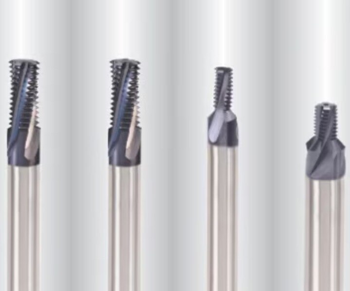
A thread mill does not force a complete thread into a hole in one axial stroke. It builds the thread through controlled circular and axial motion, giving you direct control over pitch diameter, entry, exit and cutting load. By the end, you will be able to choose the right thread-milling method, program it safely and verify whether an inaccurate thread came from the tool, machine or workpiece.
Key takeaways
- Use helical interpolation to control pitch and thread diameter.
- Match tool diameter to thread size and required radial adjustment.
- Program entry motion to prevent lead and size errors.
- Inspect pitch diameter before changing cutting parameters.
How Helical Interpolation Controls Thread Pitch and Diameter
A thread mill forms the thread by travelling around the hole while advancing along its axis, not by forcing a complete thread into the material in one axial stroke.
This helical interpolation links one programmed revolution to the programmed pitch: if the control commands 1.5 mm of axial movement per revolution, each thread turn is spaced 1.5 mm apart. The circular path sets the diameter, while radial tool-path compensation adjusts pitch diameter without replacing the cutter.
That separation gives you more direct control over threading accuracy than a fixed-pitch tap, whose lead depends on its geometry, alignment and ability to pull itself through the hole.
It also reduces the risk of chip packing in blind holes because the thread mill cuts a controlled segment and can retract through the entry path rather than carrying a continuous chip column.
The result still depends on the machine and tool, not on interpolation alone:
- Axis positioning and interpolation accuracy determine whether the programmed pitch is reproduced.
- Backlash, spindle runout and tool deflection shift the cutter from its intended path.
- Cutter wear can change pitch diameter and may be corrected with a measured size offset.
- Excessive wear or damaged flanks cannot be corrected indefinitely by offsetting.
A thread mill therefore offers adjustable errors, not automatic perfection. It produces a more controllable thread because pitch and diameter come from coordinated CNC motion that you can measure, compensate and repeat.
How Tool Diameter, Thread Dimensions and Entry Motion Set the Usable Range
Nominal thread size alone does not establish whether a cutter will work. Match the thread pitch, form, handedness and required depth, then check the cutter against the hole and toolpath.
| Thread dimension or cutter feature | What to verify | What goes wrong if it does not fit |
|---|---|---|
| Tool diameter | Smaller than the finished minor diameter, with enough radial clearance for interpolation | The cutter rubs the hole, deflects or cannot enter safely |
| Minor diameter | Provides clearance around the cutter throughout the helical path | Collision, poor chip evacuation or a damaged cutting edge |
| Pitch diameter | Can be reached through radial toolpath compensation within the cutter’s working range | The thread fails a gauge even though the nominal size is correct |
| Flute length | Exceeds the full thread depth and leaves clearance below the bottom thread | The cutter shanks out before completing the thread |
| Cutter geometry | Matches the thread form, pitch and flank angle | Flank contact becomes incomplete or dimensionally incorrect |
The cutter’s tool diameter does not define the finished pitch diameter by itself; the CNC path and radial offset do. A smaller cutter can cover several thread diameters, but each larger internal thread changes the interpolation radius and cutter engagement.
Entry motion also sets the safe range. Start with the cutter below the finished thread, use the correct helical direction for the thread hand, and leave bottom clearance for the lead-in and exit.
Enter too close to the first thread and the cutter can mark the opening, overload one flute or begin at the wrong lead position.
How to Program a Thread Mill Without Introducing Lead or Size Errors
Put the hole centre on the programmed work coordinate, then verify the tool’s centreline against that coordinate before interpolation begins. A centre error becomes runout around the entire thread; it is not corrected by changing pitch-diameter compensation.
1. Program the axial move per revolution to equal the thread pitch. Match the helical direction to the required thread hand and confirm that the circular interpolation plane, spindle direction and toolpath produce an internal or external thread rather than its mirror image.
2. Set radial engagement from the cutter diameter, thread diameter and material. Use a light radial cut for roughing, then a separate finishing orbit; excessive radial engagement deflects a small carbide mill and leaves an undersize, tapered or rough flank.
3. Enter with a tangential arc or short ramp, not an axial plunge. Bring the cutter gradually onto the flank, then complete the helix at full engagement. In a blind hole, leave clearance below the finished thread for the cutter body and its entry motion.
4. Use climb milling for the finishing pass when machine rigidity and workholding permit it. Keep the programmed milling direction consistent through the orbit; reversing it can alter the lead-in position, chip load and effective size.
5. Apply cutter compensation or a radial size offset deliberately. Measure the pitch diameter, adjust the offset in small increments, and do not use compensation to hide flank damage, severe wear or machine backlash.
6. Finish with a controlled lead-out arc before retracting axially. Do not stop the helix abruptly on the thread, because the exit mark can damage the last thread and create a measurable lead error.
Test the CNC thread milling program in air or above the workpiece, then run a reduced-feed verification cut. Confirm centre, hand, pitch, entry, exit and pitch diameter before production.
When Thread Milling Beats Tapping or Single-Point Threading
Thread milling beats tapping when you need controlled pitch diameter, lower cutting torque, or reliable blind-hole threading. It is not automatically faster: compare the complete cycle, including tool changes, entry and withdrawal, chip clearing, and the number of diameters one cutter can produce.
| Option | Accuracy and control | Cycle time and chip behaviour | Cost and application range |
|---|---|---|---|
| Thread mills | Helical interpolation limits tap-lead and alignment errors; size correction comes through the programmed path. | Single-form tools suit varied diameters; multi-form tools cut faster but demand rigid machines, accurate alignment and effective evacuation. Chips are short and controllable. | Higher tool cost, offset by one compatible cutter serving several diameters. Strong choice for hard, gummy, abrasive or interrupted materials and blind holes. |
| Cutting taps | Fast, consistent production when the hole, material and tap alignment are suitable. | Usually the shortest cycle, but long chips can pack a blind hole, damage flanks or break the tap. | Low cost per hole in stable, high-volume work; less forgiving of material changes and tap damage. |
| Forming taps | Produces a strong, chip-free thread by displacing material; requires correct ductility, hole size and lubrication. | Fast, with no chips to evacuate, but forming torque and bottoming risk rise in blind holes. | Economical in ductile materials; unsuitable for brittle or abrasive materials. |
| Single-point threading | Flexible and easy to correct, but slower because each pass removes limited material. | Excellent control and chip access, with long cycle times. | Useful for large, unusual or repair threads rather than volume production. |
Ask R.S. Tools & Engineers Pvt. Ltd. to compare cutter geometry, flute length, minor diameter and thread depth—not just price—before choosing a thread mill. Small carbide mills still need short overhang and controlled runout.
Related products
 | Hi-Performance Special Taps and Thread Milling Cutter Hi-Performance Special Taps and Thread Milling Cutter Product Details: Usage For Taping ,Threading and Cutting/Drilling Purpose Shape Straight Color Golden, Grey and Silver Material Carbide High Speed... View product → |
 | Therad Mills Product Details: Shape Straight Color Black and Silver Usage For Threading Purpose Material Carbide View product → |
How to Inspect a Milled Thread and Correct the Real Source of Error
A failed GO/NO-GO thread gauge proves only that the finished thread falls outside its functional envelope. After machining, inspect pitch diameter, pitch, lead, major diameter, minor diameter, flank angle and thread form against the drawing and thread standard. The gauge cannot identify which dimension caused the failure.
Measure these features before changing a tool offset:
- Pitch diameter: compare the measured value with the gauge result. A uniform size shift with correct pitch and form indicates radial compensation, cutter diameter, deflection or tool wear.
- Pitch and lead: measure several thread intervals. A repeating lead error points to programmed pitch, axis interpolation, backlash or servo-motion error rather than pitch diameter.
- Major and minor diameter: an isolated crest or root error indicates incorrect cutter engagement, hole preparation or cutter profile.
- Flank angle and form: damaged or unequal flanks indicate profile wear, deflection, runout or the wrong cutter.
| Finding | Likely source | Corrective action |
|---|---|---|
| Pitch diameter shifts uniformly | Size offset, cutter diameter or uniform tool wear | Adjust radial compensation after confirming form |
| Pitch varies along the thread | Axis interpolation, backlash or programmed pitch | Check machine motion, pitch data and helical code |
| Thread axis wobbles | Spindle or tool runout, hole position or entry motion | Check holder runout, overhang and lead-in |
| Flanks lose their angle | Tool wear, deflection or wrong profile | Replace the cutter; do not offset indefinitely |
Recheck with the GO/NO-GO thread gauge after correction. A size offset cannot repair a damaged flank or persistent runout.
Frequently asked questions
How does helical interpolation control thread pitch and diameter?
The CNC moves the thread mill around the hole while advancing one thread pitch per revolution. Circular motion sets the thread diameter, while axial movement sets the pitch.
How do tool diameter and thread dimensions limit thread milling?
The tool must fit inside the bore and leave enough radial clearance for the thread profile. Thread size, tool diameter, flute length, and the controller’s compensation range determine the usable range.
When is thread milling better than tapping?
Thread milling suits hard materials, large or interrupted holes, difficult-to-control chip evacuation, and applications where one tool can produce multiple thread sizes. Tapping is faster for high-volume, standard blind or through holes.
How do you correct errors in a milled thread?
Inspect the pitch diameter, pitch, flank form, and thread depth first. Adjust radial tool compensation for size errors, feed or synchronisation for pitch errors, and tool condition or alignment for profile defects.