
A drill marked HPD does not guarantee a particular hole tolerance, because suppliers use the term for different high-precision designs. By the end, you will know which measurable drill, machine, setup and cutting conditions control hole size, location, straightness and repeatability.
Key takeaways
- Verify the supplier’s HPD definition against hole tolerance, finish and tool-life requirements.
- Use point geometry and flute design suited to the material and hole depth.
- Choose carbide for rigid, productive setups; choose HSS when toughness and flexibility matter.
- Match drill diameter, holder, spindle speed and feed to the CNC setup.
Define HPD by measurable hole and tool requirements
The HPD drill meaning is supplier-specific, not a universal ISO classification. Before calling one a high-accuracy tool, verify the hole result it is designed to produce and the tool limits that support it.
1. Confirm the nominal diameter and stated diameter tolerance. Ask whether the specification applies to the drill itself or to a finished solid-drilled hole in a named material.
2. Define the solid drilling hole tolerance you need. Solid drilling commonly achieves approximately IT10–IT12; IT7–IT9 usually requires reaming, boring or interpolation after drilling.
3. Measure drill runout at the cutting edges, not only at the holder. Radial runout can enlarge the hole by nearly twice its value with a two-margin drill, before deflection and edge imbalance add further error.
4. Request the high accuracy drill tolerance, permissible runout, usable hole-depth ratio, point geometry, margin design, workpiece material and coolant requirement. These details determine whether the tool suits your application.
5. Check the complete assembly: short gauge length, rigid spindle and an accurate hydraulic, shrink-fit or collet holder. A long or poorly held drill can wander, taper or cut oversize even when the drill itself meets its specification.
How point geometry and flute design stabilise the hole
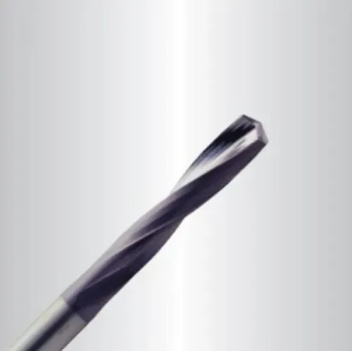
A split point drill enters centrally because its shortened chisel edge reduces the force needed to push through the surface, while its two cutting lips engage more evenly. Web thinning reduces thrust and limits entry deflection. These features improve self-centering, but they cannot correct spindle misalignment, excessive runout or an angled entry surface.
| Feature | How it stabilises the hole | Failure if mismatched |
|---|---|---|
| Point geometry and rake | Balances cutting forces and directs the lips into the material; choose rake for the workpiece | Excessive thrust, edge chipping or built-up edge |
| Web thinning | Reduces the chisel-edge load at the centre | Rubbing, heat and a wandering start |
| Drill margin guidance | The margins contact the bore wall and support diameter and straightness | Poor guidance increases taper, oversize and surface damage |
| Drill flute design | Controls chip space, cutting-edge support and chip evacuation through the hole | Packed chips raise torque, heat and radial force |
Measure runout at the cutting edges, not only at the holder. Radial runout can make the hole substantially larger than the nominal diameter, with two margins transmitting the error along the bore.
Match flute length, helix and chip space to the material: ductile alloys need reliable evacuation, while hard materials need edge support that resists chipping.
Choose carbide or HSS against the production requirement
The carbide versus HSS drill choice follows hardness, batch size and machine capability. Use carbide for hardened steel, stainless steel and aluminium when spindle rigidity, stable coolant and repeatable production justify higher cost. Choose HSS for low-to-medium batches, interrupted work or machines that cannot maintain carbide cutting speed.
| Option | Production fit | Geometry and life decision |
|---|---|---|
| Carbide | High-volume runs and hard or abrasive workpieces | Specify a split point, suitable rake and chip flutes for the material; replace it when hole drift or margin wear reaches the defined limit. |
| HSS | Lower speeds, variable jobs and less rigid machines | Use a tougher point and chip space for the workpiece; set drill tool life from measured hole diameter and surface-finish change, not breakage. |
Specify the HPD drill diameter range by nominal hole size, tolerance and depth ratio. Do not accept a diameter catalogue alone: confirm cutting-edge runout, point angle, web thinning, margin form and geometry for drilling hardened steel, stainless steel aluminium or your actual alloy.
For a small batch, trial one tool and record holes until diameter drift begins. For a long batch, calculate replacement intervals from that result and order spares. R.S. Tools & Engineers Pvt. Ltd. can help you compare carbide and HSS options against the material, machine and required batch life.
Related product
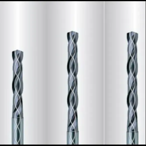
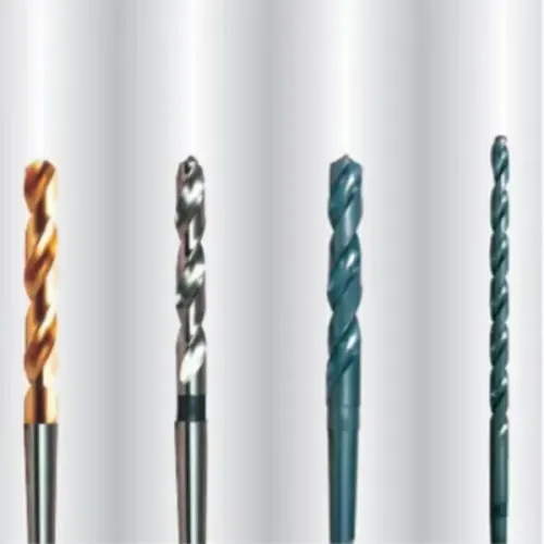
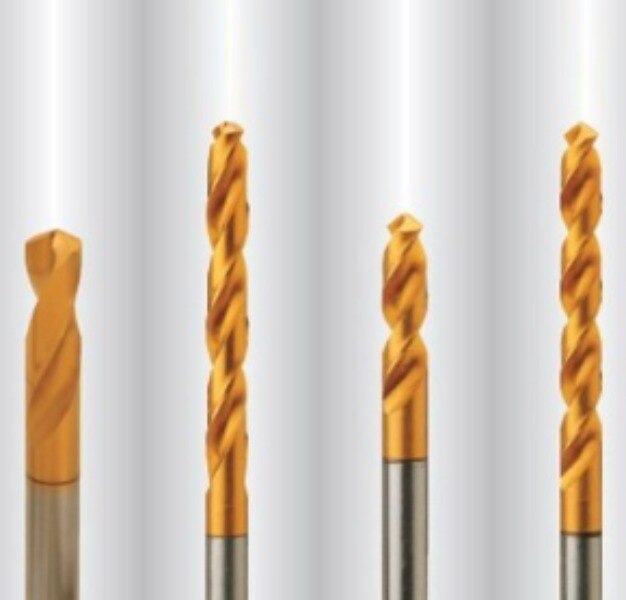
 | High Accuracy HPD Drills Product Image Supply Ability:500 Per Day Material:Carbide, High Speed Steel Usage:For Cutting and Drilling Purpose Color:Silver and Golden... View product → |
Match the drill to the spindle, holder and CNC control
A short, rigid assembly limits bending before cutting begins. Excessive gauge length lets the drill deflect under thrust, causing entry wander, taper and an oversize hole. Set the gauge length only as long as chip evacuation and access require, then measure runout at the cutting edges rather than checking the holder alone.
Holder choice matters when the tolerance is tight.
| Holder type | Strength | Risk to control |
|---|---|---|
| Hydraulic holder | Dampens vibration and provides good concentricity | Excessive clamping force or contamination can shift the setting |
| Shrink fit holder | Short, rigid assembly with low runout | Poor heating or uneven cooling can damage concentricity |
| Precision collet holder | Flexible and easy to change | A worn collet or inaccurate bore raises runout |
Control drill toolholder runout at the shank and cutting edges. Radial runout can make the hole substantially larger than the drill; with a two-margin drill, its geometric contribution can approach twice the measured radial value. A rigid spindle and machine reduce deflection, but they cannot correct a bent holder or damaged taper.
Store the CNC drill tool offset from the actual gauge line and verify it after every tool change. An incorrect length offset can produce a hole at the wrong depth, while an incorrect diameter or wear offset changes size across the batch.
Prepare the workpiece for the type of hole
Choose the hole type before choosing the HPD drill. Preparation that suits a flat, solid surface can fail at an angled entry, an interrupted cut or a cross-hole.
1. Solid drilling: Use the production drill directly on a clean, continuous face. For location-critical holes, add spot drilling with a spot angle equal to or greater than the production drill’s included point angle.
2. Blind holes: Select a drill with flute length and usable depth exceeding the required hole depth. Allow space for the drill point and chips; otherwise the hole bottoms early or packs chips against the tip.
3. Through holes: Support the exit with a backing plate when possible. Reduce breakout with a suitable point geometry and confirm that the drill’s flute length clears the workpiece.
4. Deep holes: Choose a deep-hole-capable drill and use the maker’s peck interval and retract distance for the material and coolant delivery. Excessive pecking interrupts stability; insufficient retract leaves chips in the bore.
5. Angled holes: Use angled entry drilling only after creating a perpendicular spot face, pilot feature or interpolated entry. A drill entering on one edge can walk, chip a corner and cut oversize.
6. Interrupted holes: Use a purpose-designed drill or interpolation when the cutting edge repeatedly enters and leaves the workpiece.
7. Cross-hole drilling: Treat the intersecting bore as an interrupted cut. Reduce asymmetric loading with a prepared spot, controlled entry and a drill geometry rated for cross-hole work.
Match the drill pilot hole angle to the production point angle; a narrow spot drill can leave the outer corners unsupported.
Set cutting conditions, inspect the bore and control wear
Set the drilling speed and feed from the HPD drill maker’s chart for the workpiece material, diameter and coolant method. Do not reduce feed below the recommended cutting range: rubbing at low feed generates heat, work-hardening and built-up edge, which can destabilise size.
1. Run the specified rpm and feed, then choose a peck drilling cycle only when depth or chip form requires it. Unnecessary retracts interrupt cutting and can recut chips; inadequate retracts leave chips in the bore, raising torque and scratching the wall.
For deep holes, use the maker’s peck interval and retract distance for that material and coolant delivery.
2. Apply through-tool coolant as depth increases. External coolant becomes less reliable several diameters into ductile material, where long chips can block flutes and trap heat. Check pressure, flow and chip evacuation rather than assuming coolant has reached the cutting zone.
3. Inspect the first holes and repeat at a defined interval. Measure entry diameter, diameter through the depth and location; use a plug gauge for a functional limit, but use air gauging, a bore gauge or coordinate measurement for taper, straightness, cylindricity and position. Record hole cylindricity inspection results.
Replace the drill when margin or corner wear, built-up edge, diameter drift or surface-finish change reaches the defined limit. Waiting for breakage allows precision to fail first.
Frequently asked questions
What does HPD mean for a high-accuracy drill?
HPD is supplier-specific rather than a universal ISO classification. Check the stated hole tolerance, surface finish, diameter range, material suitability and tool-life limits.
How do point geometry and flute design improve hole precision?
Point geometry controls centring and cutting balance, while flute design affects chip evacuation, heat and cutting stability. Match both to the workpiece material and hole depth.
Should you choose carbide or HSS for an HPD drill?
Choose carbide for rigid CNC setups, higher cutting speeds and consistent production. Choose HSS when the setup needs greater toughness, flexibility or impact resistance.
How do you set up an HPD drill on a CNC machine?
Match the drill to the spindle speed, feed capability, holder runout and machine rigidity. Secure the workpiece, apply suitable coolant and confirm the CNC control uses the correct tool offsets.
How do you control HPD drill wear and hole accuracy?
Set speed and feed for the material, inspect bore diameter and finish at planned intervals, and replace the drill when wear changes size, roundness, burrs or surface quality.