
Consistent CNC holes depend on more than the nominal drill diameter. You need to match the drill’s geometry and dimensions to the material, control runout and chip evacuation, then verify the hole beyond its entry diameter. By the end, you will know how to select, run and monitor a general-purpose drill without expecting it to perform a finishing operation.
Key takeaways
- Treat “General Dream Drill” as a catalogue name, not a drill standard.
- Match point geometry, diameter and length to the material and hole depth.
- Control runout, chips and breakthrough to prevent oversized or damaged holes.
- Track hole size and wear to set a reliable tool-change point.
What “General Dream Drill” Means on a CNC Machine
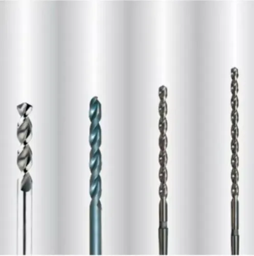
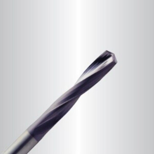
“General Dream Drill” is usually a supplier’s product or category name, not a recognised drill standard. The General Dream Drill meaning depends on the catalogue: it commonly describes a general-purpose CNC drill in a jobber drill form, but the name alone does not define its point geometry, material, coating or tolerance class.
Confirm these details before programming the tool:
- Diameter range, flute length, overall length and shank diameter
- Point angle, helix angle and margin design
- Substrate, coating and manufacturer’s diameter tolerance
- Recommended materials, hardness range, cutting data and coolant method
A drill that suits mild steel can form built-up edge in aluminium, chip in abrasive cast iron or work-harden stainless steel when feed is too low and the tool rubs. Treat the selected tool as a hole-making tool, not a finishing tool.
Solid-carbide drilling commonly produces approximately IT12–IT13 hole tolerance; IT7–IT9 usually requires reaming, boring or another finishing operation.
Expect a consistent pilot hole when the diameter, geometry, workholding and cutting data match the material. Do not expect the drill to correct spindle-to-fixture misalignment: a hole can measure correctly at the entrance yet exit tapered, angled or displaced. Check more than entrance diameter when straightness, location and hole-to-hole repeatability matter.
Match Drill Geometry and Dimensions to the Workpiece
A stable, repeatable hole starts with matching the drill to the material’s hardness, chip behaviour and required depth—not with the label “general-purpose.” Mild steel drilling needs a tough, standard geometry; aluminium drilling needs sharp, polished flutes to prevent built-up edge.
Alloy steel drilling and cast iron drilling demand greater wear resistance, while stainless steel work-hardens when the edge rubs.
| Material and condition | Geometry and construction | Selection consequence |
|---|---|---|
| Mild steel, low to medium hardness | Standard split point, medium helix, HSS or carbide substrate | A sound general drill can produce consistent holes |
| Alloy steel, higher strength or hardness | Tough substrate, wear-resistant coating, point geometry suited to interrupted cutting | A mild-steel geometry can chip or lose size early |
| Cast iron, abrasive and short-chipping | Robust cutting edges, wear-resistant substrate, air blast or coolant suited to the grade | Edge wear and oversize holes appear before the drill looks blunt |
| Aluminium, soft and gummy | Sharp edge, polished flute, high helix and non-sticking coating | Poor geometry packs chips and creates built-up edge |
| Stainless steel, work-hardening condition | Positive sharp edge and uninterrupted cutting | Rubbing from low feed or dwelling hardens the hole wall |
Check diameter, flute length, shank fit, point angle, helix angle, margin design and tool tolerance before releasing the job. At about 4×D depth, chip evacuation and drill stiffness become critical; excessive length can cause wandering, taper and oversize.
A drilled hole is not a finishing operation: solid-carbide drilling commonly achieves about IT12–IT13, while IT7–IT9 usually requires reaming or boring with a controlled allowance.
Choose Diameter, Length and the Right Hole-Making Operation
Drill diameter selection depends on the operation: use the smallest practical pilot, the nominal diameter only for a drilled-to-size hole, and a controlled undersize for reaming or boring.
| Operation | Diameter choice | Length choice |
|---|---|---|
| Pilot hole | Choose a diameter that guides the following drill without making its web rub or clog the entry. Do not assume a tiny pilot improves location. | Use the shortest drill that reaches the required depth; excessive flute length increases wandering. |
| Drilled-to-size hole | Select the nominal diameter when the expected process capability matches the drawing tolerance. Solid-carbide drilling commonly produces about IT12–IT13, not IT7–IT9. | Keep the flute length just beyond hole depth and the overall length as short as the fixture allows. |
| Hole for reaming | Leave a uniform, diameter-specific allowance from the reamer supplier’s data. Too much stock overloads the reamer; too little leaves rubbing and poor correction. | Ensure the flute length clears the hole and chips, while avoiding a long overhang. |
| Hole for boring | Drill below the boring diameter and leave enough material for the boring tool to correct size and geometry; take the allowance from the boring operation plan. | Provide access for the boring bar, not unnecessary drill reach. |
Match the shank diameter to the holder and machine capacity, then verify runout at the cutting edges; about 0.02 mm TIR is a practical carbide-drilling target. For depths near 4×D or more, prioritise stiffness, coolant access and chip evacuation over extra overall length. A drill cannot correct spindle-to-fixture misalignment, taper or a displaced exit.
Set Cutting Data and Control Runout, Chips and Breakthrough
Set spindle speed from the drilling cutting speed formula: N = 1000Vc ÷ (πD), where Vc is cutting speed in metres per minute, D is drill diameter in millimetres, and N is revolutions per minute. Excessive speed raises heat and wear; insufficient speed can increase cutting force and produce a rough, oversized hole.
Set feed per revolution from the toolmaker’s data, then calculate feed rate as feed per revolution × spindle speed. Too much feed increases thrust and breakthrough damage, while too little feed encourages rubbing, work hardening and poor surface finish.
Reduce feed as the drill exits the workpiece, especially on thin sections, to limit burrs and breakout.
Control the setup before changing cutting data. Keep carbide drill runout at the cutting edges near 0.02 mm total indicated runout or less. Excessive runout makes one margin cut harder, causing oversize, poor roundness and uneven wear; a rigid holder and clean toolholder taper also protect straightness.
At depths around 4×D and above, chip evacuation becomes a process-control problem. Through-tool coolant reaches the cutting zone and carries chips through the flutes; flood coolant can lose effectiveness in deep, ductile-material holes. Use a short, controlled peck only when chips demand it, because repeated re-entry leaves witness marks and can reduce straightness.
Watch for rising spindle load, increasing thrust, fragmented chips, oversize diameter and declining finish. If reaming follows, leave a uniform allowance from the reamer supplier’s data rather than drilling to final size.
Verify Hole-to-Hole Repeatability and Manage Tool Life
Confirm repeatability by sampling holes at set intervals, measuring diameter and location, and plotting the results against your drawing limits. A carbide general drill commonly produces IT12–IT13 drilling tolerance; IT7–IT9 usually requires reaming, boring or another finishing operation.
Use one inspection plan throughout the run:
- Measure diameter with a calibrated plug gauge, bore gauge or air gauge, and record actual values rather than only pass/fail results.
- Check hole location with a CMM, vision system or functional gauge tied to the part datums.
- Measure drill runout at the cutting edges before production; keep total indicated runout near or below 0.02 mm for carbide drilling.
- Compare roundness and surface finish when diameter begins to drift, because a worn margin can enlarge or distort the hole before the drill breaks.
- Log spindle load, thrust, chip shape and cycle count for tool wear monitoring, then replace the drill at a defined limit instead of waiting for failure.
Excessive runout makes one cutting edge work harder, producing oversize holes and uneven wear. If the hole will be reamed, specify a uniform, controlled drilling allowance from the reamer supplier’s data; do not use the drill to chase final size.
Involve R.S. Tools & Engineers Pvt. Ltd. when material, hardness, hole depth, coolant, tolerance or expected tool life falls outside your proven setup. Ask the supplier to confirm point geometry, helix, coating, substrate, diameter tolerance and recommended cutting data for the exact workpiece.
Related product
 | General Dream Drills Supply Ability:500 Per Day Product Type:Dream Drills Material:Carbide Shape:Straight Color:Silver and Grey Usage:For Cutting and Drilling Purpose View product → |
Frequently asked questions
What does “General Dream Drill” mean on a CNC machine?
It is usually a supplier’s product or category name, not a recognised drill standard. Confirm the drill’s geometry, material, coating and tolerance class before use.
How do you choose a General Dream Drill for a workpiece?
Match the drill diameter, point geometry, length, material and coating to the workpiece material, hole depth and required tolerance.
Which cutting data and setup checks improve hole quality?
Set speed and feed for the drill and workpiece, then check tool runout, chip evacuation, coolant delivery and breakthrough conditions.
How do you verify repeatability and manage drill life?
Measure hole diameter and position across multiple parts, inspect the cutting edges, and replace the drill when wear causes results to leave specification.