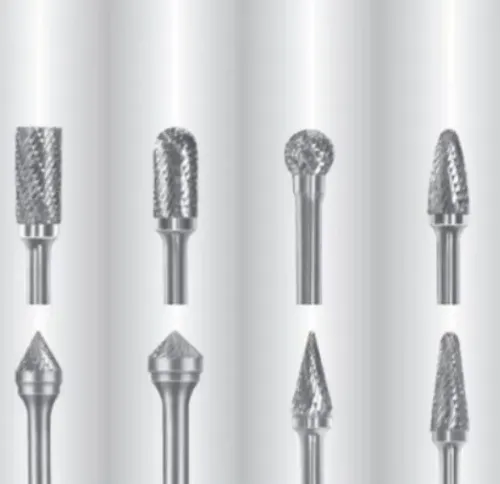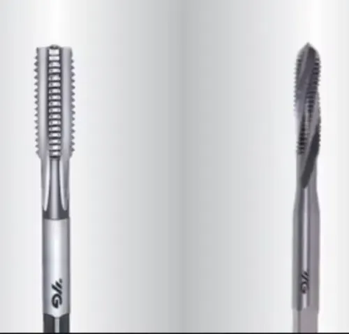

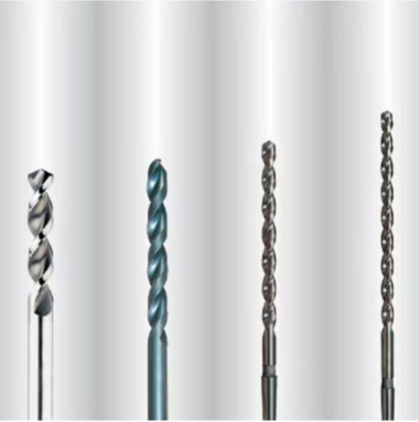
“Worm pattern drill” does not identify one universal industrial cutting-tool specification. You will learn how to recognise the geometry, match it to wood or metal-drilling work, calculate a starting speed and feed, and specify the dimensions and tool material needed for a safe purchase.
Key takeaways
- Treat worm pattern as an auger geometry, not a universal industrial drill standard.
- Control self-feeding before the lead screw pulls the tool into the work.
- Match diameter, flute length, shank, machine, and hole depth before purchase.
- Set speed and feed from tool material, workpiece, diameter, and machine limits.
What “Worm Pattern” Means—and Why the Name Needs Clarification
“Worm pattern drill geometry” usually describes a worm-pattern auger for wood, not a universal industrial drill standard. Its threaded lead screw sits ahead of the cutting lips, while helical flutes behind the lips lift chips from the hole.
The screw pulls the tool into timber, creating self-feeding action; a standard twist drill has continuous cutting edges and a passive point that relies on applied feed pressure.
Do not place a buying order from the name alone:
1. Request a drawing, catalogue designation, or stated application. Ask whether the tool is a wood auger or a recognised metal-drill geometry, such as a DIN- or ISO-designated stub drill or jobber drill.
2. Confirm the intended workpiece. A wood auger’s screw and lips suit fibrous timber; they do not define a controlled drill for steel, stainless steel, cast iron, or aluminium.
3. Reject any quotation based only on “worm pattern.” That phrase establishes neither point angle, helix angle, flute count, tolerance, coating, substrate, nor workpiece range.
The word “worm” can also refer to the tooth form used in worm-gear manufacture. There, it describes a gear element rather than drill geometry, so a worm-gear component’s machining process may involve separate drilling, boring, reaming, or forming operations. A supplier needs the actual drawing or application before matching a tool.
How the Lead Screw Moves Chips—and Where Self-Feeding Becomes Dangerous
The lead screw pulls the auger into timber while the cutting lips shear fibres. Helical flutes provide chip evacuation by carrying the cut material out of the hole, so a self-feeding drill starts deep holes in wood and construction timber with less manual pressure. That convenience increases torque and feed force.
Self-feeding becomes dangerous when the screw grabs suddenly. The workpiece can rotate, the tool can break through uncontrollably, or packed chips can seize the flutes.
| Failure | What happens | Control |
|---|---|---|
| Grabbing | Torque spikes and the tool jerks forward | Clamp the work securely |
| Breakthrough | The screw pulls the lips through the exit face | Reduce feed near the exit surface |
| Torn fibres | Thin sheet, laminates, and backed panels delaminate | Use a backing board for clean breakthrough |
| Unsupported point | The screw pulls without stable cutting support | Use a pilot hole, stepped process, or different geometry |
The lead screw is a cutting feature, not merely a centring aid. Filing, grinding, or flattening it changes feed behaviour; the auger may stop self-feeding predictably and demand excessive manual pressure.
For thin sheet drilling and breakthrough, choose support before speed. A backing board prevents the exit face from flexing, while a pilot hole or stepped process helps when the screw point lacks support.
Do not use a wood worm auger in steel, stainless steel, cast iron, aluminium, or abrasive alloys. Those materials require a metal-cutting drill; the wrong geometry causes rapid edge damage, seizure, or breakage.
Selecting the Tool: Diameter, Depth, Shank, Machine, and Hole Requirement
Specify the actual drill diameter and usable flute length, overall length, and shank size and chuck compatibility before choosing a tool. Nominal diameter does not equal maximum hole depth: flute reach, chip packing, rubbing, and available clearance set the practical limit.
Match shank form and capacity to a hand drill, drill press, CNC spindle, or other machine; check runout.
| Option | Selection basis | Limitation |
|---|---|---|
| Stub-length drill | Stub drills provide rigidity for short holes | Insufficient reach for deep holes |
| Jobber drill versus long drill | Jobber drills suit general-purpose reach; long drills add depth | Long drills deflect more easily |
| Carbide drill | High rigidity and production accuracy | Breakage risk rises with poor alignment or shock |
| Core drill | Produces a larger hole with an annular cut | Leaves a core and needs suitable support |
| Step drill | Suits thin sheet and multiple diameters | Not a substitute for deep, precise holes |
State the required hole tolerance, entry and exit condition, blind or through-hole status, interrupted cuts, and whether a reaming operation will follow. For a worm-gear part, specify the initial drilled hole separately from later boring or reaming; worm threads require dedicated hobbing and form-tool operations, not a worm-pattern drill.
Choosing Tool Material and Calculating a Safe Starting Speed and Feed
Substrate determines how much heat, shock, and deflection a drill can tolerate. HSS versus cobalt HSS versus carbide is a choice between toughness, heat resistance, and production life—not a simple quality ranking.
| Material | Strength | Limitation |
|---|---|---|
| HSS | Tough, economical, and suitable for general-purpose drilling | Loses hardness sooner as cutting temperature rises |
| Cobalt HSS | Greater heat resistance for difficult steels and stainless steel | More brittle and less forgiving than standard HSS |
| Carbide | High rigidity, wear resistance, and long production life at higher cutting speeds | Sensitive to shock, interrupted cuts, poor alignment, and breakage |
For metal drilling, calculate spindle speed in revolutions per minute as: 1,000 × cutting speed in metres per minute ÷ (π × drill diameter in millimetres). Feed rate in millimetres per minute equals spindle speed multiplied by feed per revolution.
Obtain cutting speed, feed per revolution, point geometry, coolant instruction, and coating recommendation from the tool maker for the actual material and diameter.
For a wood worm auger, use the manufacturer’s lower speed range, not a small-diameter metal-drill chart. Its screw lead, large diameter, and torque demand magnify overspeed risk.
Set feed for the hole condition: through-holes need reduced feed near breakthrough, blind holes need chip clearance, deep holes need pecking where specified, and interrupted cuts demand extra caution.
Matching the Drill to the Industrial Operation and Purchase Specification
Use a self-feeding wood auger only for securely clamped timber in an industrial drilling application where its screw point and cutting lips suit the fibres.
Do not use it as a universal tool for manual metal drilling, CNC steel work, blind holes, thin laminates, or interrupted cuts; it can grab, tear the exit face, pack chips, or break.
For CNC metal drilling, write a complete CNC drilling specification: recognised DIN or ISO product standard, or the maker’s geometry; substrate; point angle; coating; diameter tolerance; shank; usable length; coolant method; workpiece material; hole depth; and whether it is a through-hole versus blind hole. “Worm pattern” does not define these variables.
R.S. Tools & Engineers Pvt. Ltd. can add value by checking those missing details before quoting instead of matching an ambiguous label to a catalogue item. Confirm the actual cutting diameter and fluted length, not just the nominal size.
Use this drill selection checklist before releasing the order:
- Confirm the drawing number or catalogue code.
- Measure the shank and cutting diameter.
- Verify chuck, spindle, torque, and machine capacity.
- Clamp the workpiece securely.
- Run the manufacturer’s speed and feed data.
- Inspect the first hole for size, burrs, breakout, rubbing, and chip packing.
Related product
 | Worm Pattern Drills Color:Silver Shape:Straight Usage:For Cutting and Drilling Purpose Material:Others View product → |
Frequently asked questions
What does “worm pattern drill” mean?
It usually describes a worm-pattern auger for wood, with a threaded lead screw ahead of cutting lips and helical chip-lifting flutes behind them.
Why can self-feeding become dangerous?
The lead screw can pull the drill rapidly into the work, overload the machine, damage the hole, or cause loss of control when the setup lacks adequate restraint.
What should you check before selecting a worm-pattern drill?
Check the required hole diameter and depth, workpiece, drill-point geometry, flute length, shank size, machine capacity, chuck or holder, and chip-clearance needs.
How do you choose a starting speed and feed?
Use the tool material, workpiece material, drill diameter, manufacturer’s cutting data, and machine limits; begin conservatively and adjust for chip formation, torque, and heat.