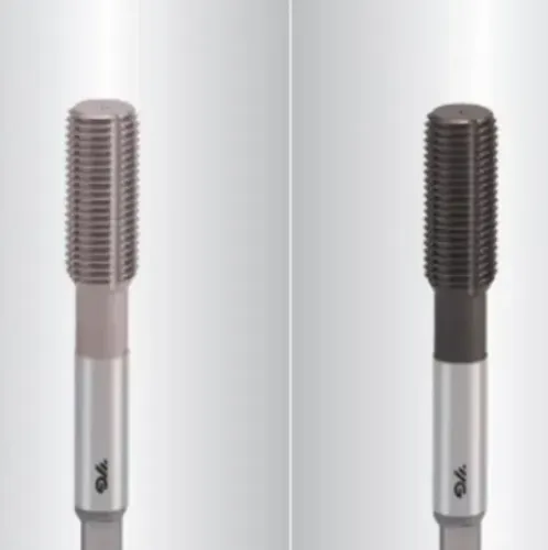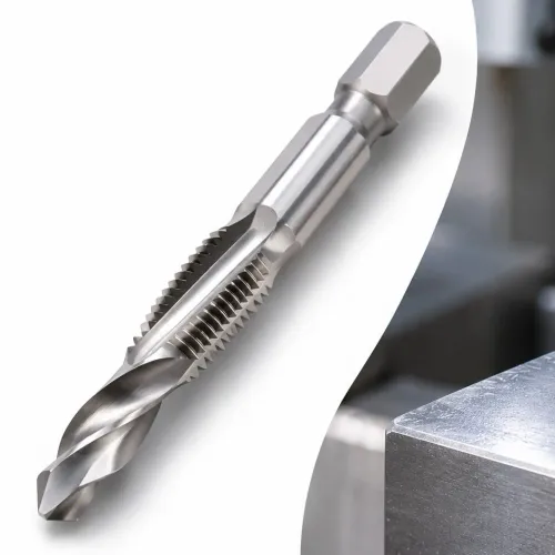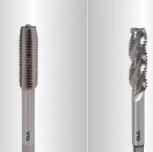


A carbide tap is not automatically the best choice for every workpiece, hole depth or CNC machine. By matching the tool material, thread geometry, forming method, pre-hole, machine rigidity and trial criteria, you can select a tap that produces gauged threads without trading small gains in wear life for sudden breakage.
Key takeaways
- Match carbide grade, edge preparation and coating to the workpiece.
- Confirm thread standard, fit, pitch, depth and hole geometry before ordering.
- Choose cutting or forming taps before calculating the pre-hole diameter.
- Run a controlled trial to verify thread quality, tool life and breakage risk.
Match the Tap Material and Grade to the Workpiece
Material determines whether carbide delivers longer, cleaner production or fails without warning. Choose the tap grade, edge preparation, coating and cutting data for the workpiece, not just the thread size. A cast iron grade with abrasive inclusions, for example, rewards carbide’s wear resistance; a tough, shock-loaded steel can fracture it.
| Option | Material or condition | Safer choice and reason |
|---|---|---|
| Solid carbide | Abrasive cast iron, aluminium, composites, powder metals and selected hardened steel | High wear resistance and consistent holes on rigid CNC equipment; use a workpiece-specific grade and coating |
| Carbide-tipped | Abrasive material with interrupted cutting or less-than-perfect rigidity | Carbide resists wear at the edge while the tougher body better absorbs shock |
| HSS-E or powdered metal | Tough low-carbon or alloy steel, nickel alloys, unstable setups or frequent tap reversal | Greater toughness reduces sudden breakage, even if tool life is shorter |
| HSS-E with polished geometry | Aluminium or ductile nonferrous material on a less rigid machine | A sharp, low-friction edge controls built-up edge without carbide’s bending sensitivity |
For aluminium, specify a sharp polished edge and low-friction surface; a heavy wear coating can worsen built-up edge. Nickel alloys generate heat and resist cutting, so use a grade, coating and speed recommendation made for that alloy rather than a general-purpose carbide tap. Hardened steel needs geometry rated for its hardness range.
Use solid carbide only when alignment, axial control and rigidity are dependable; chatter, runout, deep blind holes and interrupted cuts make HSS-E or powdered metal safer. Include the cost of a broken tap and scrapped workpiece in the comparison.
Specify the Thread Standard, Fit and Hole Geometry
Thread standard and finished fit determine the tap’s thread form, flank angle, pitch and tolerance class. Metric ISO threads, Unified threads, pipe threads and STI threads are not interchangeable: a tap for an M6 × 1 thread cannot produce a 1/4-20 UNC thread or an NPT sealing thread.
Specify the standard, nominal size, pitch, class of fit and whether the thread is internal or insert-related.
Use this selection checklist:
- State the required internal-thread class, such as 6H for a metric ISO thread, rather than ordering only by nominal diameter.
- Treat designations such as ISO 2/6H or 6HX as tap tolerance information, not proof that the finished hole will pass inspection. Verify production threads with the specified GO/NO-GO plug gauges.
- Choose a spiral-point tap for a through hole, where chips can exit ahead of the tap. Choose a spiral-flute tap for a blind hole, where chips must travel back toward the shank.
- Use a long plug chamfer for easier starting and lower load per tooth; use a bottoming chamfer when usable thread must reach close to the hole bottom.
- Add the chamfer length, full-thread depth and chip-clearance space to the programmed hole depth.
For a cutting tap, start with the maker’s drill chart; M6 × 1 is often near 5.0 mm, but strength, tolerance and thread percentage can change it. A forming tap needs a larger, maker-specified pre-hole. Mis-sizing it raises torque and can break the tap.
Choose Between Cutting and Forming Taps Before Sizing the Pre-Hole
A 5.0 mm drill is a starting point for an M6 × 1 cutting thread, not a universal answer. Use cutting taps when the material produces manageable chips or lacks the ductility needed to flow; choose forming taps when a sufficiently ductile material can withstand plastic displacement without cracking.
| Choice | Thread-making action | Select it when | Starting hole rule |
|---|---|---|---|
| Cutting taps | Remove material as chips | You need predictable chip evacuation, or the workpiece is brittle or insufficiently ductile | Estimate tapping drill diameter as nominal diameter minus pitch; M6 × 1 is about 5.0 mm, then confirm the tap maker’s chart |
| Forming taps | Displace material into the thread profile | Aluminium, low-carbon steel, brass or another ductile alloy can flow without splitting | Use the forming-tap manufacturer’s specified, usually larger, pre-hole range; do not apply the cutting-tap formula |
| Cold-forming roll taps | Form the thread without chip removal | Chip control matters and the machine can handle higher forming torque | Size from the maker’s material-specific chart and verify the resulting thread with gauges |
Treat the pre-hole as a torque and tool-life control, not merely a way to maximise thread percentage. A hole that is too small for forming taps can create excessive torque, oversize threads or tap breakage; a hole that is too large reduces thread engagement.
Select the chart value after accounting for material strength, hole tolerance, coating and drilling method, then check the finished thread with GO and NO-GO plug gauges.
Check Rigidity, Alignment, Depth and Coolant Before Choosing Carbide
A solid-carbide tap needs a rigid CNC setup with synchronized spindle rotation and axial feed. Use rigid tapping when the machine maintains the programmed thread lead; if it cannot, a tension-compression holder can reduce axial loading but cannot correct poor rigidity, incorrect pitch programming, or excessive runout and misalignment.
Chatter, interrupted cuts and frequent reversals can chip carbide before wear becomes the problem.
Check these conditions before selecting it:
- Measure spindle, collet and holder runout at the tool shank; small taps have little ability to absorb angular error.
- Confirm the holder controls axial and radial movement rather than relying on a worn collet.
- Calculate blind-hole depth from the drill point, mouth chamfer, required full-thread depth, tap chamfer length and chip-clearance space.
- Match the chamfer to the job: a long taper spreads load but leaves more incomplete thread; a bottoming chamfer reaches deeper and raises entry-load risk.
- Direct coolant into the flutes and provide a path for chips to leave the hole. Packed chips can create a torque spike during reversal and fracture the tap.
| Condition | Carbide suitability | Safer response |
|---|---|---|
| Rigid CNC with reliable rigid tapping | Suitable | Verify programmed pitch and tool holding |
| Uncertain runout or angular alignment | Poor | Correct the setup before tapping |
| Deep blind hole with limited chip space | High fracture risk | Increase clearance or use a tougher tap |
| Hand-operated or flexible machine | Poor | Use a more tolerant tap construction |
Validate the Selection with a Controlled Production Trial
Run each candidate on the same machine, material lot, hole depth, coolant and thread quantity, then compare total cost per accepted threaded hole. Keep the pre-hole diameter and cutting data fixed unless the manufacturer specifies a different window for that tap.
| Option | Purchase and operating profile | Cost and risk to compare |
|---|---|---|
| Solid-carbide tap | High wear resistance, but low tolerance for runout, chatter and interrupted cuts | Strong value when one tap produces many consistent holes; a sudden fracture can scrap the workpiece |
| HSS-E taps | Tougher and more forgiving on variable production or less-rigid machines | Lower tool cost and lower breakage exposure, but more frequent replacement can raise labour and downtime |
| Powdered-metal taps | Better toughness and edge support than many standard HSS-E taps | Useful where interrupted cuts or material variation makes carbide fracture likely |
| Carbide-tipped taps | Carbide cutting edges with a tougher supporting body | Compare edge life against the risk of tip damage and the cost of replacing the tool |
Record holes per tap, cycle time, tool-change minutes, torque or spindle-load trend, and results from GO/NO-GO plug gauges. A designation such as ISO 2/6H or 6HX does not prove the finished thread will gauge correctly; wear, hole size, alignment and coolant still change the result.
Cost each failed hole, broken tap, extraction attempt, setup delay and rejected part. R.S. Tools & Engineers Pvt. Ltd. can help assemble a matched trial set, but your production records—not nominal tap price—must decide the winner.
Related products
 | Carbide Threading Taps Shape:Straight Material:Carbide Usage:For Tapping Cast Iron Color:Silver and Grey View product → |
 | Cold Forming Roll Tap Cold Forming Thread Tap Product Image Color:Black and Grey Product Type:Cold Forming Material:Carbide Shape:Straight View product → |
Frequently asked questions
How do you match a carbide threading tap to the workpiece?
Choose the carbide grade, edge preparation, coating and cutting data for the material’s hardness, abrasiveness and toughness. Abrasive cast iron suits carbide wear resistance, while shock-loaded steel increases fracture risk.
What thread and hole details must you specify?
State the thread standard, nominal diameter, pitch, class or fit, thread depth, blind or through-hole condition, entry chamfer and any relief requirements.
When should you choose a cutting tap or a forming tap?
Choose a cutting tap when the application needs chips removed from the hole. Choose a forming tap when the material supports cold forming and the resulting thread profile, torque and pre-hole size are acceptable.
What must you check before using a carbide threading tap?
Check machine and workholding rigidity, spindle alignment, tapping depth, chip evacuation and coolant delivery. Carbide needs stable conditions because misalignment and shock can cause sudden fracture.
How should you validate a carbide threading tap selection?
Run a controlled production trial and record thread gauge results, surface finish, torque or load, cycle time, tool life, chips and any edge damage before full-scale use.
Related products
 | Hi-Performance Special Taps and Thread Milling Cutter Hi-Performance Special Taps and Thread Milling Cutter Product Details: Usage For Taping ,Threading and Cutting/Drilling Purpose Shape Straight Color Golden, Grey and Silver Material Carbide High Speed... View product → |
 | High Performance Taps Product Details: Color Golden, Grey and Silver Usage For Taping ,Threading and Cutting/Drilling Purpose Shape Straight Material Carbide View product → |
 | Hi- Performance Spiral Pointed Taps Hi- Performance Spiral Pointed Taps Product Details: Usage For Taping ,Threading and Cutting/Drilling Purpose Color Golden, Grey and Silver Shape Straight Material Carbide View product → |
 | Straight Flute Taps Product Type:Threading Tools Material:Carbide Usage:For Tapping STI Threads Soft Materials Color:Silver and Black Shape:Straight View product → |