
A combo tap removes a separate drill-to-tap handoff, but it does not remove the need to select the right thread, pre-hole, material data and tapping cycle. By the end, you will know how the tool works, how to run it safely and when its shorter process is preferable to separate drilling and tapping.
Key takeaways
- Match the tap to thread size, pre-hole diameter, and workpiece material.
- Program feed to match thread pitch during the tapping section.
- Leave chip space and depth allowance when tapping blind holes.
- Check thread size, pitch, depth, and damage before releasing parts.
What a combo tap does in one spindle operation
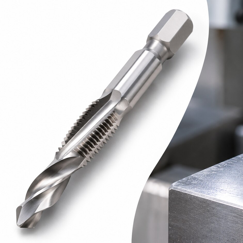
The practical combo tap meaning is a single tool that drills and taps the same hole in one continuous spindle operation. A drill-and-tap tool first uses its drill point to create the pilot hole, then its threaded cutting section follows to form the internal thread.
It does not drill a full-size hole before tapping, so a separate pilot drill is not required when the workpiece, hole depth and tool geometry match the manufacturer’s specification.
This combined drilling and threading sequence keeps the tool on the programmed axis from entry through thread formation. Tool change elimination removes the retract, tool exchange and re-entry needed between separate operations.
That reduces cycle time and improves positional consistency because the second tool does not have to locate a hole created by the first; the gain becomes more noticeable across many small holes or thin sections.
Use a rigid tapping cycle when the CNC machine, spindle, holder and control support synchronized rotation and feed. Do not apply ordinary twist-drill data to the drilling portion: the drill diameter is designed around the thread’s minor-diameter requirement, and the threading section often sets the usable speed and feed window.
Monitor spindle load or torque during production, because a worn tap section can produce excessive torque or damaged threads even while its drill point still appears sharp.
How to choose the thread, pre-hole and workpiece material
Confirm the drawing before selecting the tool: identify the nominal diameter, pitch, thread form, tolerance class and hole depth. “M8” is incomplete without its pitch and tolerance; M8 × 1.25 is metric coarse, while M8 × 1.0 is metric fine.
- Metric threads state pitch in millimetres; for inch threads, calculate pitch as 25.4 divided by the TPI.
- UNC denotes Unified National Coarse and UNF denotes Unified National Fine. Confirm the stated class, such as 2B, before ordering.
- Match the combo tool’s thread designation exactly. Do not substitute a separate tap-drill chart when the tool maker specifies a different pilot diameter.
For a 60-degree thread, calculate the starting pre-hole as Dpre ≈ D − Kp, where D is nominal diameter, p is pitch, and K is selected for the required thread percentage.
A conventional 75% metric starting point for M8 × 1.25 is 8 − 1.25 = 6.75 mm, but use the combo tool maker’s chart because its drilling point and threaded section may require another diameter. A higher thread percentage increases torque and tool load.
Material determines whether the tool cuts or displaces metal:
| Material condition | Suitable process | Main check |
|---|---|---|
| Ductile, malleable steel or aluminium | Cold-forming | Sufficient elongation, forming-tool compatibility and a larger specified pre-hole |
| Brittle cast iron, abrasive alloy or low-ductility material | Cutting | Chip space, coolant and a cutting-thread geometry |
| Hardened or work-hardening material | Cutting only if rated | Hardness, heat generation and torque limit |
Cold-forming is the wrong choice when the material cracks, work-hardens severely or cannot flow into the thread profile.
How to program feed, speed, alignment and coolant
Clamp the workpiece rigidly and align the combo tool to the hole axis before setting the cycle. Any runout or deflection shifts the pilot hole and makes the threading section cut unevenly.
1. Set the spindle speed from the tool maker’s recommended cutting speed for the actual material and tool diameter. Do not substitute ordinary twist-drill speed data.
2. Use rigid tapping when the CNC, spindle, holder and control support positive synchronization. Program tapping feed to match the thread: feed in mm/rev equals pitch in millimetres; feed in inch/rev equals 1 divided by threads per inch.
3. Apply coolant before entry and maintain delivery at the cutting zone. Drilling needs heat removal and chip control; tapping needs low-friction lubrication reaching the forming thread. Poor coolant application can cause built-up edge in aluminium or galling in stainless steel.
4. Feed continuously through the drilling and threading sections at the specified synchronized rate. Use pecking only when the tool maker permits it; an unnecessary retract can damage the transition between the pilot and thread.
5. At the programmed thread depth, stop axial feed, reverse the spindle in synchronization, and withdraw without dwelling. A floating holder can absorb small axial errors, but it cannot replace rigid tapping or correct a poorly aligned drilling cycle.
6. Control chips with the recommended flute direction, coolant flow and withdrawal strategy. Packed flutes raise torque and can break the tool.
Drilling data alone cannot set this cycle: the same speed or feed that suits the drill point can overload the threaded section. Use the manufacturer’s combined-tool data for cutting speed, feed, depth and reversal settings.
How to manage blind holes and check thread quality
Blind holes demand more clearance than through-holes because chips have nowhere to escape. Choose a tool whose flute form and flute length provide adequate chip evacuation, then compare its cutting length and chamfered or unthreaded tip with the required usable thread depth.
A programmed depth equal to the nominal hole depth does not guarantee a full thread to that depth.
1. Confirm the drawing’s usable thread depth, bottom clearance and pilot-hole depth. Keep the tool’s cutting length above the required full-thread zone; otherwise the chamfer may leave incomplete threads at the bottom.
2. Check the flute form against the material and hole depth. Through-holes are more forgiving because chips exit below the workpiece, while blind holes can pack chips, raise torque, gall the thread, tear the surface or break the tool.
3. Monitor spindle torque during tapping. A steady rise indicates chip packing, insufficient bottom clearance, misalignment or a dull edge. Use pecking or chip-clearing only when the tool maker permits interruption; stopping a tap inside the hole can damage both tool and thread.
4. Inspect finished threads with a GO/NO-GO plug gauge made for the specified internal-thread standard. The GO gauge must pass to the specified usable depth, while the NO-GO gauge must not enter beyond its allowed turns. Also verify pitch diameter and thread form; a screw entering the hole alone does not prove thread quality.
When a combo tap is the right production choice
Choose a combo tap for thin sheet threading, light-gauge parts and short thread engagement where eliminating a tool change matters more than achieving deep, full-thread depth. It is not the best substitute for separate drilling and tapping in thick sections or deep blind holes.
| Option | Best fit | Main limitation |
|---|---|---|
| Combo drill-tap | Thin sheet and short threads | Narrower process window; limited full-thread depth |
| Separate drill plus tap | Thick sections, deep holes and maximum thread quality | Adds a tool change and positional-error risk |
| Cold-forming roll tap | Ductile materials needing chip-free threads | Requires the correct pre-hole and sufficient material flow |
The choice between cutting thread versus forming thread affects pitch diameter, torque and tool life. A combo tool’s drill point leaves the minor-diameter region required by its threading section; do not substitute an ordinary tap-drill size without checking the maker’s data.
Replace it based on torque or spindle-load change as well as visible drill wear, because a worn tap section can produce undersized or torn threads.
Before ordering, give R.S. Tools & Engineers Pvt. Ltd. or another supplier:
- Thread designation, pitch, tolerance class and required usable depth.
- Workpiece material, thickness, hole type and expected production volume.
- The manufacturer’s pre-hole diameter, synchronized feed and speed data.
- Whether you need a cutting tap or a roll tap, then confirm the material supports forming.
Related product
 | combo tap Product Image Material:Carbide Color:Silver and Grey Usage:For Cutting, Shaping and Grinding Purpose Shape:Straight View product → |
Frequently asked questions
What does a combo tap do in one spindle operation?
A combo tap uses its drill point to make the pilot hole, then its threaded section forms the internal thread without a tool change.
How do you choose a combo tap for a job?
Match the thread standard and pitch to the drawing, confirm the required pre-hole diameter, and select a tool suited to the workpiece material.
How should you program a combo tap?
Set spindle speed for the tool and material, synchronise feed with thread pitch, maintain tool alignment, and apply coolant suited to the cutting operation.
How do you check a blind-hole thread made with a combo tap?
Confirm the tool reaches the required thread depth without bottoming, then inspect the thread with the specified gauge or mating fastener and check for chips, tearing, and incomplete threads.