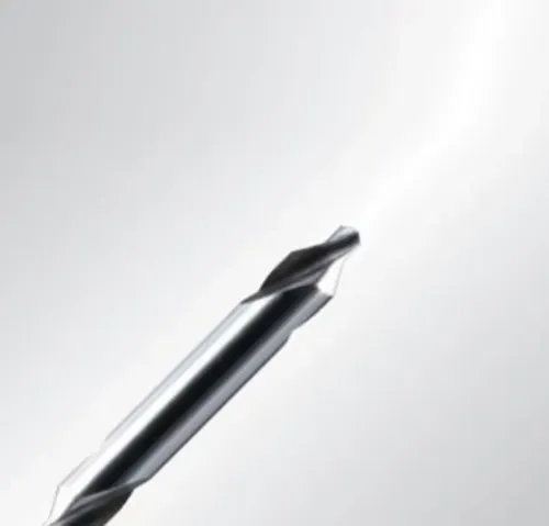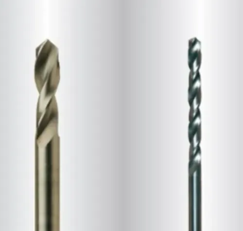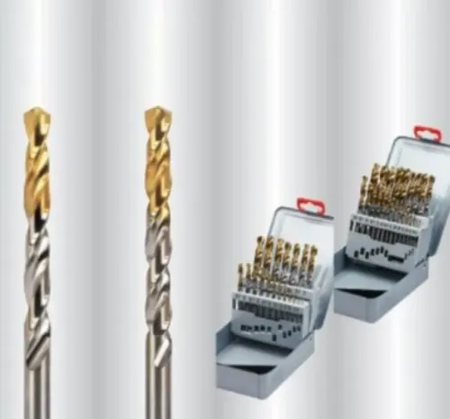
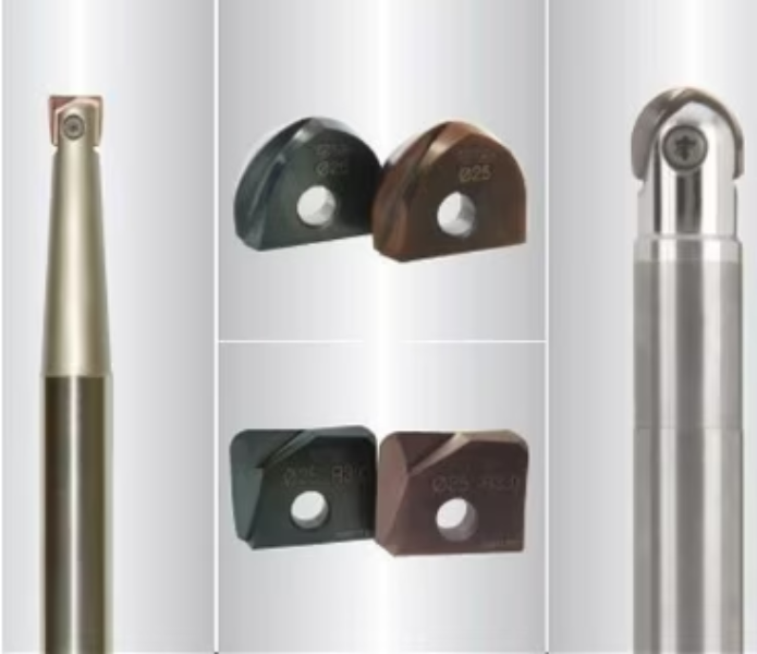
Complex surfaces introduce challenges that conventional straight-line milling does not. Mould cavities, contoured profiles, curved components and intricate three-dimensional features require a cutting tool capable of following programmed toolpaths while maintaining surface quality.
A 3-Dimensional Milling Tool should therefore be selected according to the geometry being produced rather than only cutter diameter. R.S. Tools & Engineers Pvt. Ltd. serves machining and manufacturing requirements in Delhi where appropriate milling-tool selection can help improve both productivity and finishing consistency.
What Is 3-Dimensional Milling?
Three-dimensional milling uses simultaneous or sequential machine-axis movements to generate contoured surfaces and complex component shapes.
It is commonly associated with CNC machining because programmed toolpaths allow cutters to follow surfaces that would be difficult to manufacture through conventional manual operations.
Applications can include:
- Die and mould cavities
- Curved component surfaces
- Automotive tooling
- Precision engineering parts
- Prototype components
- Complex pockets and profiles
- Finishing of sculptured surfaces
Different stages of these operations may require different cutter geometries.
Match the Tool to the Machining Stage
One common mistake is expecting a single milling tool to handle roughing, semi-finishing and final finishing equally well.
During roughing, the priority is normally efficient material removal while maintaining acceptable tool loading. Semi-finishing prepares the component for the final toolpath, while finishing focuses more heavily on dimensional accuracy and surface quality.
The cutter should reflect those requirements.
Ball-nose and other profile-specific cutters, for example, may be appropriate for certain contoured finishing operations, while different geometries can be preferable when removing larger amounts of material.
Tool Selection Factors for Delhi CNC Workshops
Before choosing a 3-Dimensional Milling Tool, review five important factors:
- Workpiece material: Steel, hardened steel, aluminium and other materials require different cutting considerations.
- Surface geometry: Deep cavities and curved surfaces may influence tool reach and cutter shape.
- Required finish: Fine finishing normally requires different toolpath and cutting strategies from roughing.
- Machine rigidity: High-performance tooling needs stable machine conditions.
- Tool overhang: Excessive projection can increase vibration and deflection.
These factors should be evaluated together rather than separately.
Avoiding Chatter and Poor Surface Finish
Chatter is particularly troublesome during 3D milling because vibration patterns can become visible across finished surfaces.
Reducing unnecessary tool overhang, maintaining rigid workholding and selecting appropriate cutting parameters can improve stability. Toolpath strategy also matters. Abrupt changes in engagement may increase cutting loads and create inconsistent surface results.
Delhi manufacturers working with moulds, dies and precision components should evaluate milling performance based on complete machining results rather than cutter life alone.
The right 3-Dimensional Milling Tool should support the required geometry, surface finish and cycle-time objectives without creating unnecessary secondary finishing. Matching cutter design to the actual machining stage is one of the most effective ways to achieve that balance.